1. #### GRID / MESH
A **mesh** divides a geometry into many elements. These are used by the CFD solver to construct **control volumes**.
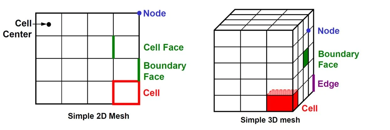
**Terminology:**
• Cell = control volume into which domain is broken up.
• Node = grid point.
• Cell centre = centre of a cell.
• Edge = boundary of a face.
• Face = boundary of a cell.
• Zone = grouping of nodes, faces, cells
• Domain = group of node, face and cell zones.
Points to consider when generating a mesh are:
• Mesh resolution
• Type of mesh
• Computer resources
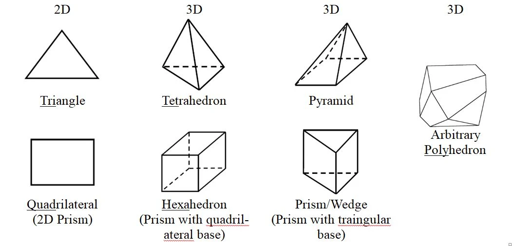
The **shapes of control volumes** depend on the** capabilities of the solver**.
- Structured-grid codes use quadrilaterals in 2D and hexahedrons in 3D flows.
- Unstructured-grid solvers often use triangles (2D) or tetrahedron (3D), but newer codes can use arbitrary polyhedrons.
2. #### Grid Structure
The purpose of the mesh generator is to decompose the flow domain into control volumes.
The primary outputs are:
• cell vertices
• connectivity information
Precisely where the _nodes_ are relative to the vertices depends on whether the solver uses, for example, cell-centred or cell-vertex storage. Further complexity is introduced if a staggered velocity grid is employed.

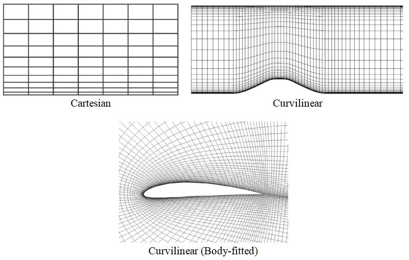
3. #### Grid Types
- Structured Grids
- Cartesian
- Curvilinear
4. #### Block-structured Grids
a) Matching
b) Non-matching
c) Chimera (composite)
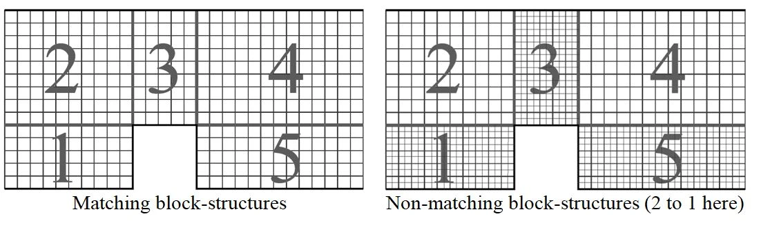
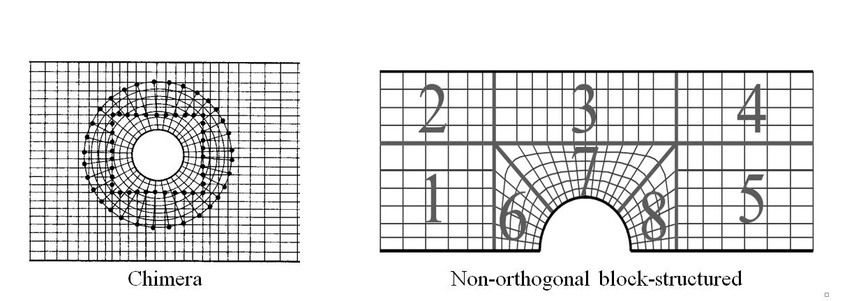
Generally, multiple blocks are useful in maintaining a structured grid configuration around complex boundaries.
- generally desirable to avoid sharp changes in grid direction (which lead to lower accuracy) in important and rapidly changing regions of the flow, such as near solid boundaries.
- One should also strive to minimise the non-orthogonality of the grid.
https://www.manchestercfd.co.uk/post/all-there-is-to-know-about-different-mesh-types-in-cfd
#CFD